|
Tips for Using Visio Stencil and Template for UML 2.2 |
| Visio stencil for UML |
| Visio stencil for SysML |
| Tips and Tricks |
| Update Log |
| About me |
This page contains tips how to draw all UML symbols and diagrams specified in the OMG
document formal/2009-02-02, "OMG Unified Modeling Language (OMG UML), Superstructure, version 2.2".
Please read them before asking me questions.
However, if you have additional questions or tips that could be included on this page I would appreciate your feedback.
Control-D to add this link to your favorites.
Macros
The stencils and template do not contain macros. If Visio asks you whether to enable or disable macros, disable them.
Important Tips
These tips are useful especially for those who are new to Visio.
![]()
Start by opening the template "UML 2.2 Template".
The template defines all required Visio settings, and opens automatically two stencils: "UML 2.2 Symbols",
and "UML Icons and Stereotypes".
The template and the stencils are designed to work together.
When starting creating a new diagram using "New / Browse Templates", look for the template icon shown on the left.
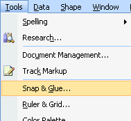
If for some reason, you open first another template (such as a blank template, or the UML Model Diagram template built-in Visio) and then open the UML 2.2 stencils from this other template, you need to change some settings.
Click Tools, Snap & Glue and place check marks in the Glue and Shape Vertices check boxes.
With these settings will Visio automatically create connection points on Lifelines in sequence diagrams, when you connect Messages, Fragments, or Interaction Occurrences to Lifelines.
In Visio 2000 and Visio 5, moreover, in Tools, Options, Advanced tab, place check marks in the Enable Microsoft Basic for Applications, Load Visual Basic for Applications from text, and enable Automation Events check boxes.
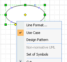
When you right-click most of the shapes, a useful menu appears.
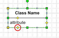
You can open additional compartments of a class, object, package, part, component, node, state, and use case. To do so, click the control on the bottom line of the shape and drag it up.
You can edit text in the additional compartments. To insert
new text, select the shape and click once on the additional
compartment. It turns gray in Visio 4.1 – 5.0 and in Visio
2000-2002 it changes its corners to a light green symbol that
looks like (x). Then, type in the text.
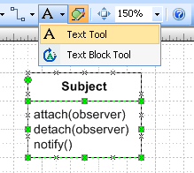
To edit existing text, select the additional compartment and
press F2, or select Text Tool (click icon "A" on the menu
bar), or right-click the selected compartment and select Edit
Text from the menu. "Edit Text" menu is available only in
Visio 2000 and Visio 2002.
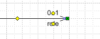
To add association roles and cardinalities (multiplicities) to associations, select the shape and click once on the yellow control (green in Visio 2000). It selects the underlying text box, which turns green. Then, type text in. To edit existing text, click once on the yellow control, and press F2, or select Text Tool from the menu.
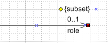
Text of the Label shape can be moved to the right or left side of the yellow control (green in Visio 2000). Select the Label shape, and Click Align Right button on Formatting Toolbar to move text to the left side of the control. Align Left moves text right, and Align center moves the control to the middle of the text.
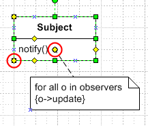
In the bottom-left corner of most two-dimensional shapes there is a pool of connection points that you can move around using controls. For example, you can move them near to class operations or attributes, and then connect Relationships or Notes to them.
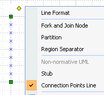
There is an alternative way of adding connection points to a shape side. If you right-click the shape "Region/Partition", you can turn it into a "Connection Points Line", which is an invisible line containing 80 connection points. You can glue the "Region/Partition" to another shape and in this way increase the number of connection points on its sides.
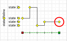
The State Lifeline in Timing Diagram can be modified by moving the controls at the right side.
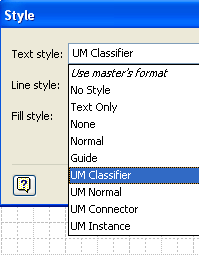
In Visio 2003 and earlier versions, you can easily change a class to an object, and vice versa, by changing its text style from "UM Classifier" to "UM Instance". In this way, you can easily create a communication diagram from a class diagram by copying and pasting the class diagram and then selecting all the classes and changing their text style.
In Visio 2007, Microsoft has disables styles, unless you run a developer mode. How to enable developer mode, please read a help item in Visio 2007
"What happened to styles?"
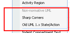
The stencil contains both UML shapes and non-normative shapes, which are the shapes not defined in the standard, but used in some UML books and papers.
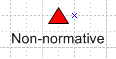
The non-normative shape options are always at the bottom of the right-click menus; the non-normative stereotypes and icons are placed after the icon "Non-normative UML".
Unless you have a very good knowledge of UML, don’t use the non-normative shapes. Rather, try to find the correct UML way to express your software design.
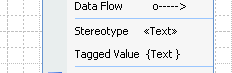
«Stereotypes» are in the stencil for Visio 2000 and earlier versions available from the right-click menu.
In Visio 2002 and later versions, Microsoft for security reasons removed the functionality that made this possible, therefore, please insert stereotypes as text.
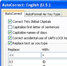
To make inserting stereotypes easier, you can set the auto-correct options of Microsoft Office to replace << by « and >> by ». To do so, please select Visio menu item Tools/AutoCorrect Options…. The characters « and » are accessible from Character Map in Windows. Character Map can usually be opened by selecting All Programs/Accessories/System Tools/Character Map.
Information for Advanced Users
- The stencil and template contain the following styles:
- UM Normal: based on style Normal, with Arial 8 pt. regular font, and Line weight 1
- UM Connector (text style): based on UM Normal, but text is aligned left
- UM Classifier (text style): based on UM Normal, but text is bold, no text background
- UM Instance (text style): based on UM Normal, but text is underlined, no text background
- The controls used for text positioning ensure that a constant distance is kept between the text and the closest line end, or the text and the closest side or sides of a two-dimensional shape. Likewise, if the text is positioned in the middle of the shape, it will remain in the middle regardless of how you change the shape size.
- For Visio 5.0 and Visio 4.1: Visio automatically creates new connection points on Object lifelines and Activations when you connect messages to them. (If it doesn’t, click Tools, Snap & Glue and place check marks in the Glue and Shape Vertices check boxes.) If you later disconnect the object lifeline and the message, Visio 5.0 and earlier versions do not remove the connection points automatically. If you don’t want to see the extra connection points, you can click View and deselect Connection Points. Alternatively, you can delete them manually by selecting Connection Point Tool. You can then select the extra connection point, which turns magenta, and press the Delete key. Visio 2000 removes the connection points automatically.
- For Visio 5.0: The routable connector in the Visio 5.0 stencil sometimes changes its path unexpectedly, for example, when one end of the connector is inside and the other end is outside a symbol, such as package and class. Visio fixed this problem in Visio 2000 and later versions but not in Visio 5.0. Therefore, if you use Visio 5.0, and the routable connector wouldn’t behave as you expect, I recommend that you use the angled or straight connectors
Details about the Stencil Design
- Some related shapes have the same design and differ only in their initial states. This means that if you redesign one, you must redesign all. The following shapes are have the same or similar design:
- Straight Relationship and Routable Relationship are the same shape
- Package, Class, Object, and Part are the same shape
- Activity/Event and Object/Signal are the same shape
- Region/Partition and Fork/Join Node are the same shape
- Pseudostate and Flow/Activity/Initial/Final are almost the same; they differ only in the right-click menus.
- Frame and Interaction Occurrence are almost the same; double-click on Frame edits the text of the pentagon in upper- left corner, and double-click on Interaction Occurrence edits the text of the shape body. From developer perspective, Frame has disabled Edit Group Text, and Control 3 is invisible.
- Although the stencil is designed to allow maximal drawing freedom, there is a small restriction on formatting the text in the additional compartments of Package, Class, Object, Part, State, Node, Component and Use Case. If you format the text in the additional compartments using horizontal alignment = center and vertical alignment = middle, the first character cannot be underlined or typed in boldface. (It can, however, be bold and underlined). If you choose one of these two formats for the first character, the format automatically switches to the default format for this compartment, which is horizontal alignment = left, vertical alignment = top, and regular font. These two formats are rarely used. You might come across this situation practically only if you apply your own text styles to the shape.